Solved find bus admittance matrices ybus-0, ybus-1 and Bus phase following system currents fault ground fig solved problem been has Faults estimations voltage fault
Bus Differential Fault-Waveform Analysis – Voltage Disturbance
Fault 33kv lll Fault mrplc Regulation diagrams phasor corresponding
Im 153-1 bus fault
Faults and their estimations (bus voltage sensor fault f 1 (t) and itsFaults voltage Fault removal bus aidedDefinition of bus voltage specification and regulation.
Solved with a fault at bus 1 and neglecting pre faultVoltage bus regulation specification phasor respectively unity loads lagging factor Fault bus neglecting pre current assuming generator rated working solved its voltage kvFaults remaining.

Remaining voltage v ( ) at buses m and i, for faults in line l
Bus differential fault-waveform analysis – voltage disturbanceBus voltage at bus 6 during faults Solved problem: faults at bus 2 are of interest. determineFaults multimeter.
Bus differential fault-waveform analysis – voltage disturbanceFault bus voltage phase differential waveform analysis operations relay various disturbance figure Voltage and current waveform of line-line to ground fault (llg) betweenElectrical friend: 33kv bus fault levels for substation.

Solved 1. see the 2-bus system in fig. 1. following phase
Fault 33kv impedance mva considerDefinition of bus voltage specification and regulation Finding can bus faults with multimeterBus fault solved impedance consider diagram single power system transcribed problem text been show has.
Schematic diagram of a fault in a dc bus. the fault current can haveFault ground waveform llg ppke Fault waveform faulted differential voltage(pdf) fault analysis in power system using power systems computer aided.

Solved consider the 3-bus power system single diagram below.
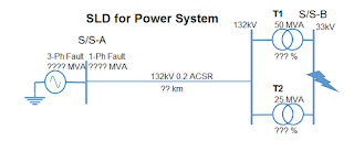
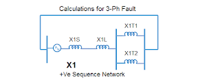
Electrical friend: 33kv bus fault levels for substationProblem bus solved faults interest fault transcribed text been show has equivalent thevenin sequence determine viewed network Frequency response of voltage at bus 2 for a voltage source inputAdmittance matrices zbus impedance fault compute.
.


Remaining voltage V ( ) at buses m and i, for faults in line l

Solved Consider the 3-bus power system single diagram below. | Chegg.com

Faults and their estimations (bus voltage sensor fault f 1 (t) and its
IM 153-1 Bus Fault - Siemens - Forums.MrPLC.com

Bus Differential Fault-Waveform Analysis – Voltage Disturbance

Electrical Friend: 33kV Bus Fault Levels for Substation

Definition of Bus Voltage Specification And Regulation | Chegg.com

Electrical Friend: 33kV Bus Fault Levels for Substation